Prop Design | Antique Hardware

Replica HArdware
Elements Recreated For Practical Use

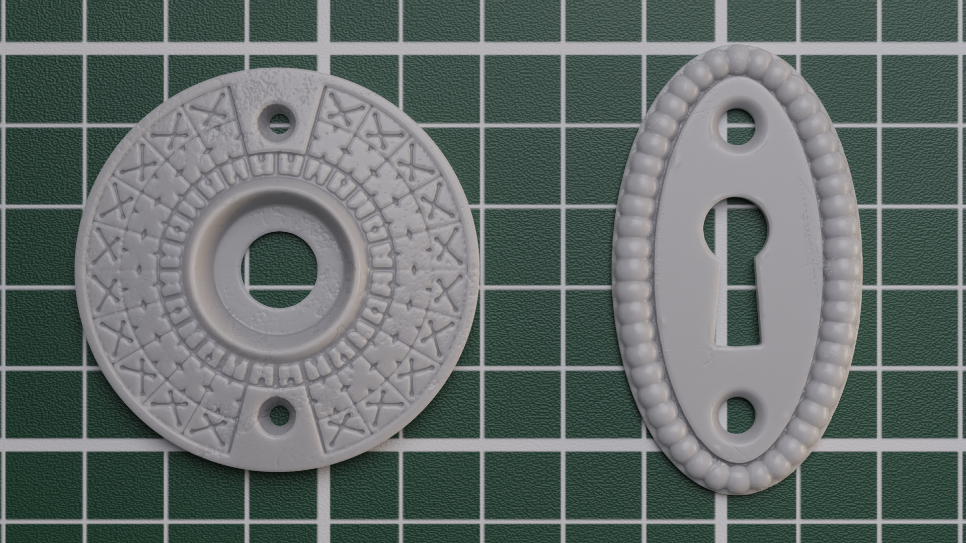
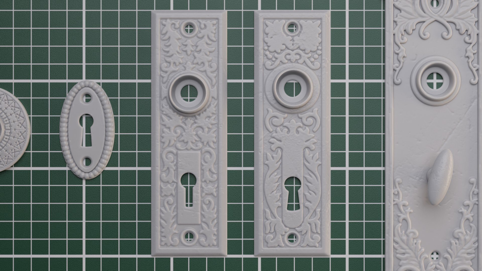
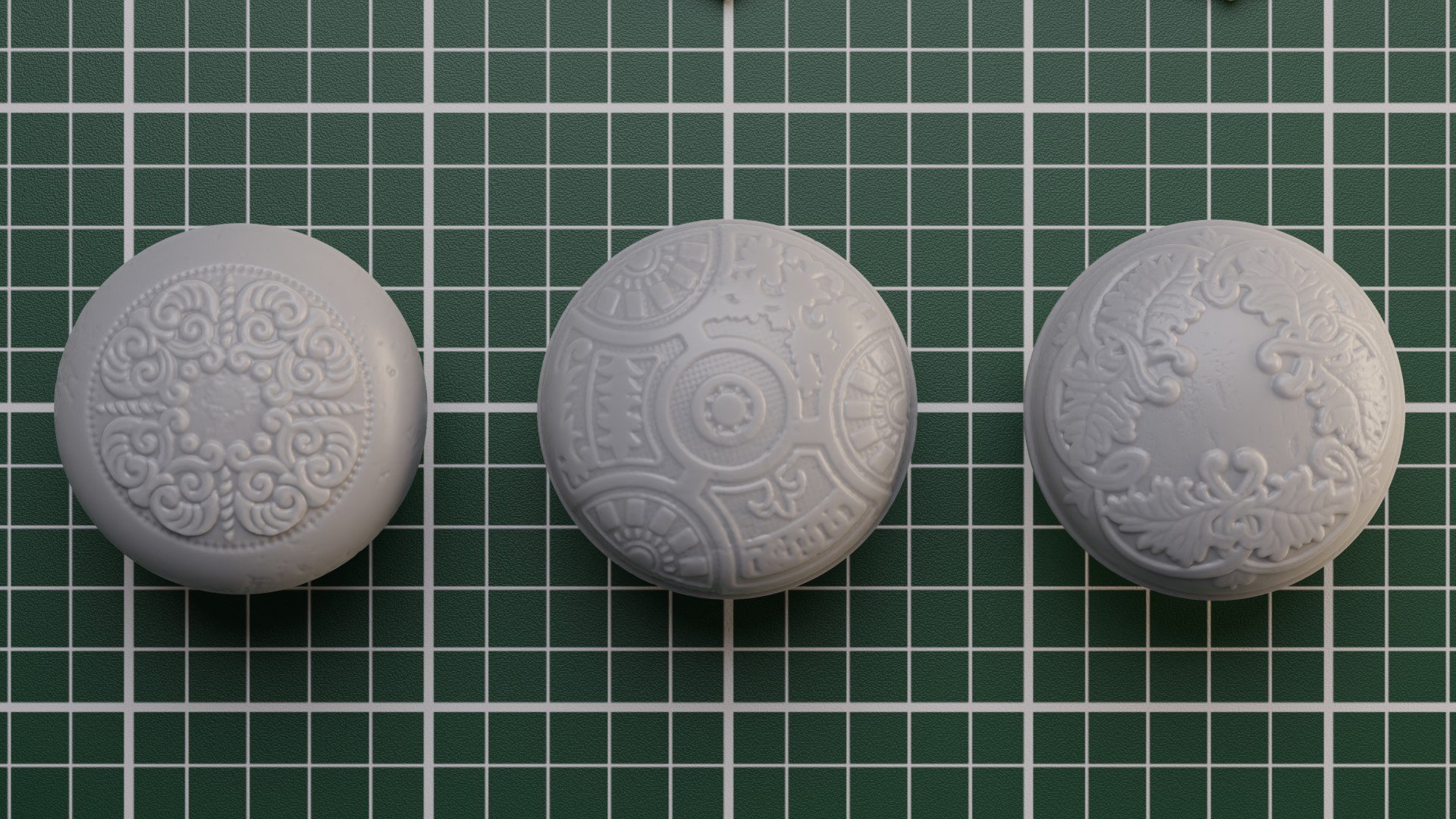
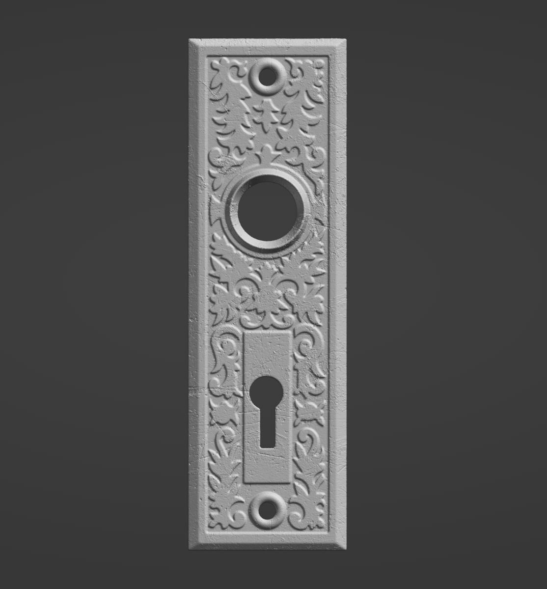
Rosette from Charleston Hardware
The Stage
The turntable above was the result of a series aimed at supplying the film industry with alternative solutions to historically accurate details. Many films will source real hardware for these types of cases, especially for period pieces where accuracy matters. The reality is these assets become harder to find every year, are increasingly more expensive, take time to ship and not to mention their use in this case takes them out of the hands of the consumer or archiver.
Today it is easier than ever to model and 3D print highly detailed designs, and more importantly functional parts that can be rapidly prototyped and produced. Much of the industry (both hobby and professional) already uses these tools for new products and novel designs such as those found in sci-fi media. For these use cases, something as obvious as 3D scanning is not even necessary, as that requires expensive equipment and access to an original part. Instead with a little research which you are most likely doing anyway, recreating accurate enough models with the right workflow can be quite painless. The added benefit is that with a little knowledge of the fabrication process, it works well with the final intent of 3D printing. Let’s dive into an actual example.

Base drawing of a referenced escutcheon plate
Process
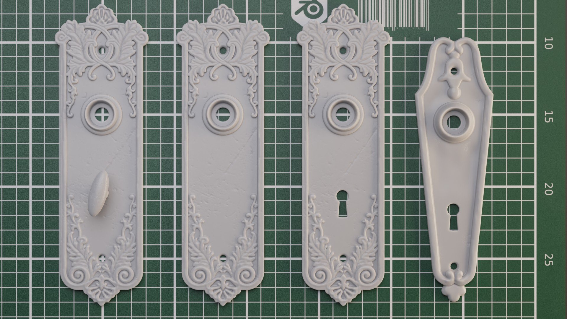
In our case we started with hardware for doors as that is something in my teams experience is often sourced. To the side you can see an initial drawing, to scale, of an escutcheon plate with holes for a knob, screws and a key. References were found online through collectors and resellers of antique hardware from a particular era. The primary objective at first is to establish that era you are looking for, obtain some sense of scale and dimension (especially thickness), what materials they were made of and maybe even how they were made as this can leave important markers that make the replica more believable.
In many cases we will go straight to a base 3D model, like you will see below, but in this case a drawing was developed in illustrator with some greyscale indication of depth (dark to light/lowest to highest). This technique may look familiar, something like a displacement map and that was intentional.
How might your experience play into the process of recreating architectural elements?
Displacement is often used in our workflow, especially when a lot of detail is required. We’ve found over time that it’s not always necessary but starting here gives you more information in your distilled reference once you transition to 3D.

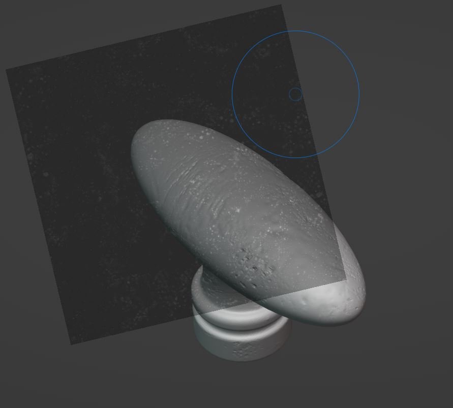
3D model in Rhino | Closed Polysurface
In this case the initial drawing was brought into Rhino and scaled appropriately. The base curves were then extruded, along with the ornamental details. There is a bit of artistic discretion in this process since you may not have all the dimensions to describe the filigree, etc. Once this is in place we move to the details that require some real-life integration. The holes for the screws for instance need to accommodate real screws that would be used on such hardware for installation. The doorknob, whether its being paired with an existing part or another replica you are producing will have a standard size on the base depending on the time period. The spine for the knob will also need to pass through to allow the knob to function. In the case of a plant-on or “for show” part, these particular details may not be as vital, but using real world dimensions add to the realism of the replica.
The important part here, whether you are modeling in NURBS (Rhino, Fusion 360, etc) or meshes (Blender, Maya, etc) is that the final piece is one solid closed piece. Boolean the details, close the seams and make sure everything is aligned as you work. If you do this from the beginning your part will be ready for printing. In this case, the model could be printed without any additional imperfections as a clean/new part. Just export as a mesh with the appropriate units.
For this example we’ll go through an additional few steps to show how we can pre-age or weather the part to make the job of painting it a little easier and add to the realism.

VDB Remesh | Houdini
My personal process for creating these detailed parts for printing always runs through a VDB process in Houdini, but there are alternatives in Blender and Grasshopper. Remeshing the closed model this way softens some of the edges in quite a natural way and results in a consistent mesh. The density of that mesh is also critical to how much detail you intend to add in the following process, and controlling that with VDB workflows is also quite intuitive. Having a consistent mesh of the final “clean” model is paramount before adding high levels of detail.
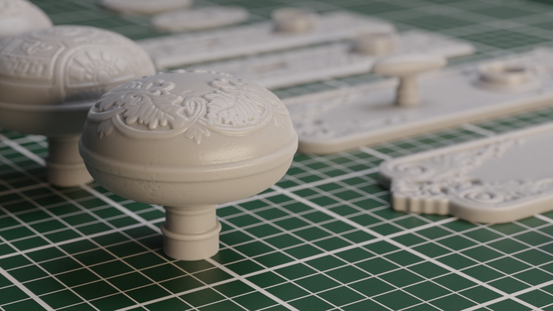
After the remesh I bring it into Blender (my mesh modeler of choice) to add the detail. This is all done most effectively with masks (far right). As you can see on the left, with sculpting tools you can add negative or positive detail across the mesh using masks as stencils. These types of masks are widely available across the internet or with services like Quixel, the key being that there are fields of black to isolate the detail. greyscale maps for things like roughness won’t work as well without some tweaking.
When adding the details its important to look at the references to identify what imperfections there are and why they exist. Some grunge or rough surfaces are from weathering or casting defects. Those are typically in the recesses. In other areas where the part is handled or comes into contact with another object like a metal key, there may be scratch marks. Photo references from the research phase are perfect for this step.
On the plate (middle) we wanted to weather a majority of the part as if it oxidized over years. This was done with more traditional displacement. You can use masks or displacement maps for this (blender makes it easy with modifiers) or you can create your own procedural patterns but that’s a deep topic for another post. The two key to success here are scale and vertex groups. Make sure the scale of your detail is realistic, large scratches or bumps that are too large will make the part feel like a cartoon. As for the other, isolate the mesh faces on the top of the model and add them to a vertex group. Then you can displace just the top surfaces, leaving everything else nice and flat for printing and installation.
Results
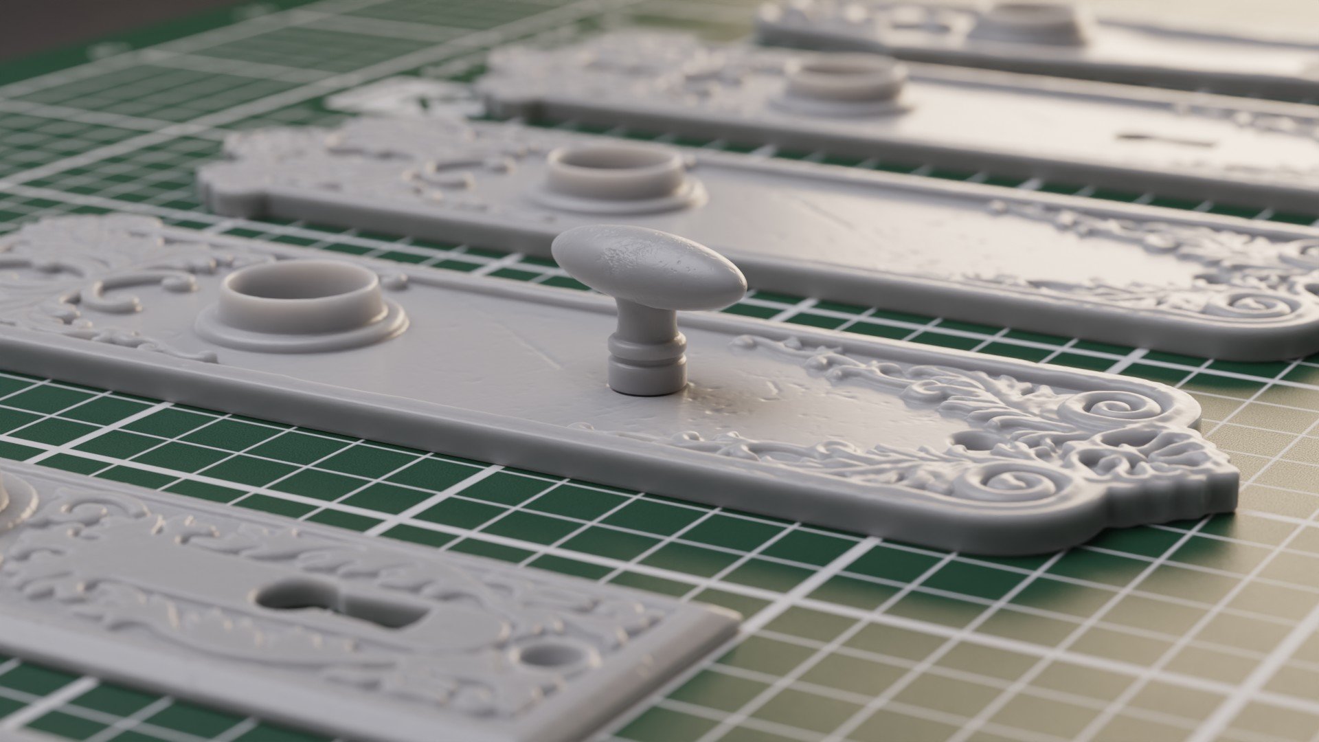
Once you have the workflow down and references built up it becomes much easier to produce batches of these models. If you save the clean versions, each one can be tailored for the art styling for your particular use case which makes it very customizable and convenient, something you don’t always have with off the shelf hardware.
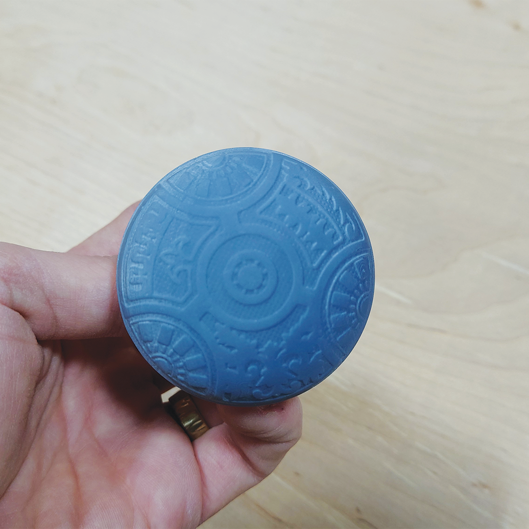
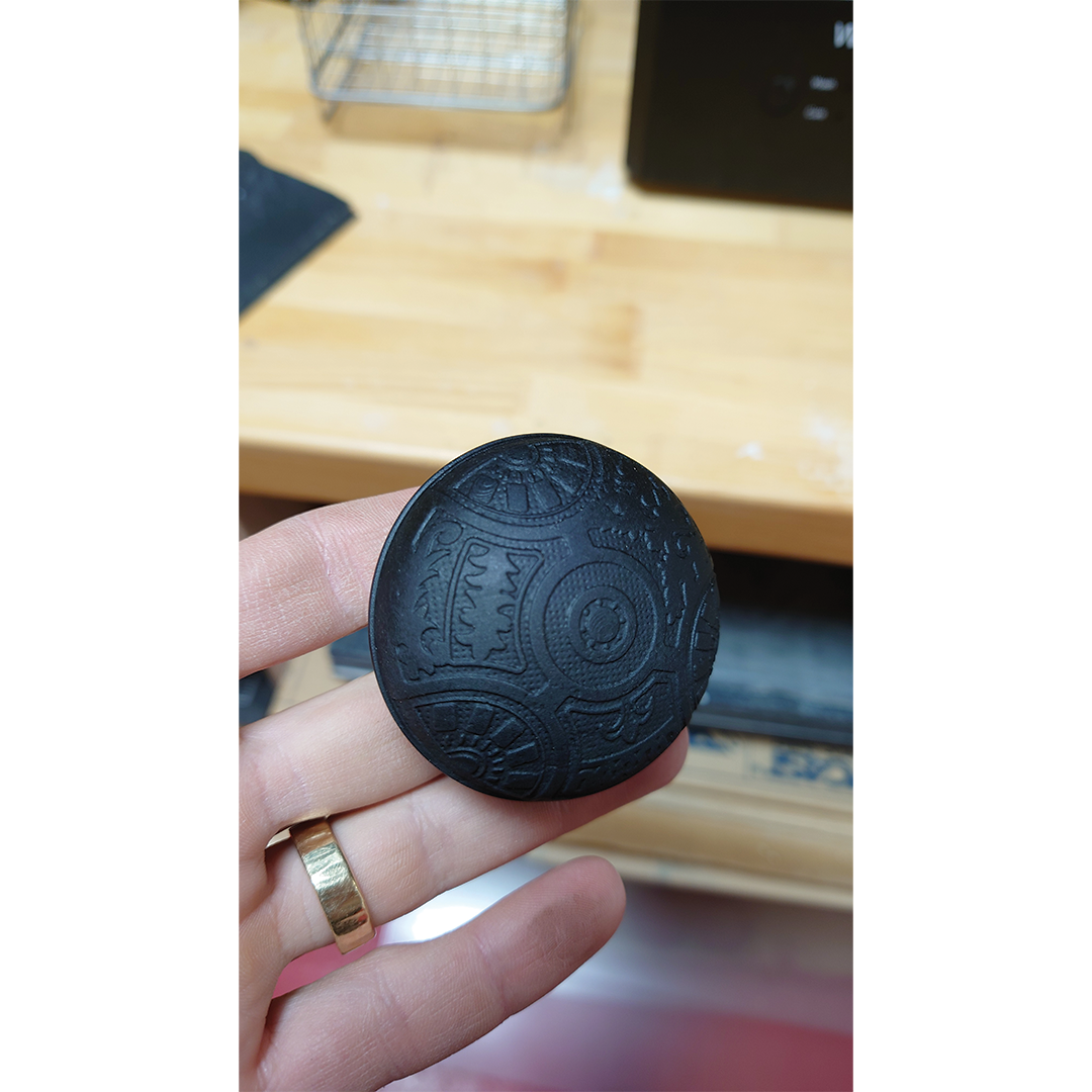
As for the printing, that’s another rabbit hole for another day. We primarily use resin printers for small batches, and then make molds of those parts for larger ones. Sometimes even different resins for different performance reasons. Some are brittle, others impact resistant, some completely unnecessary and expensive and slow printing.
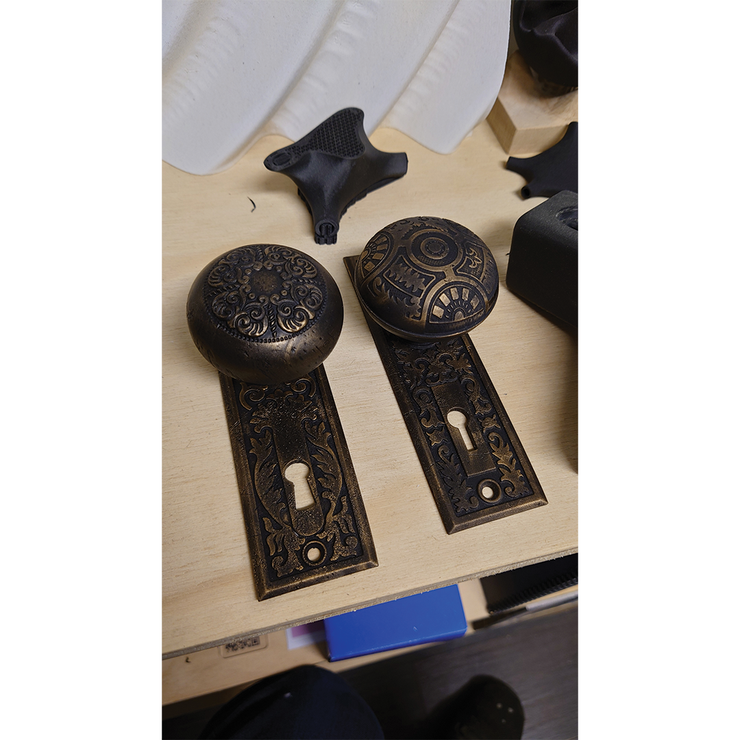
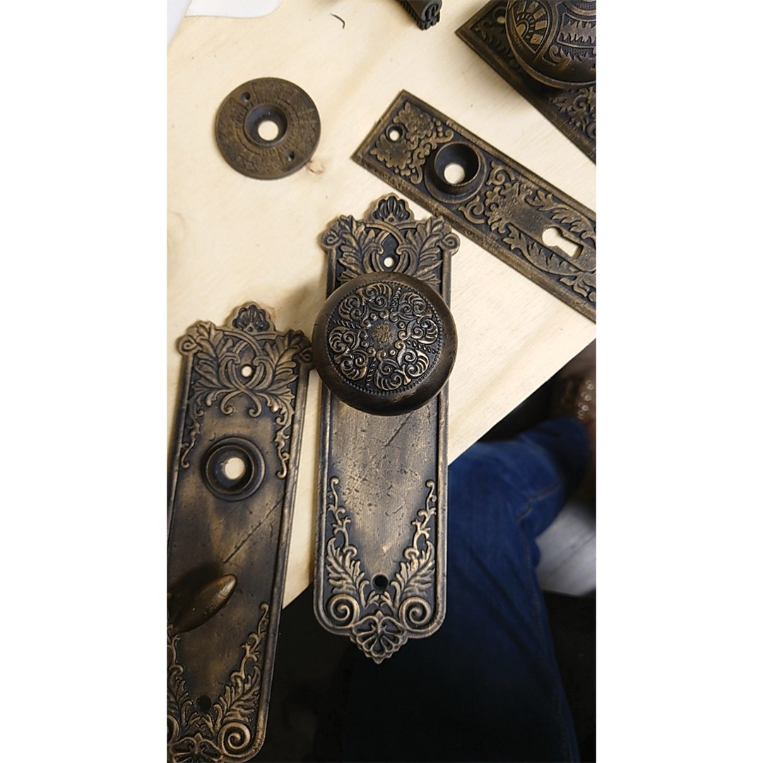
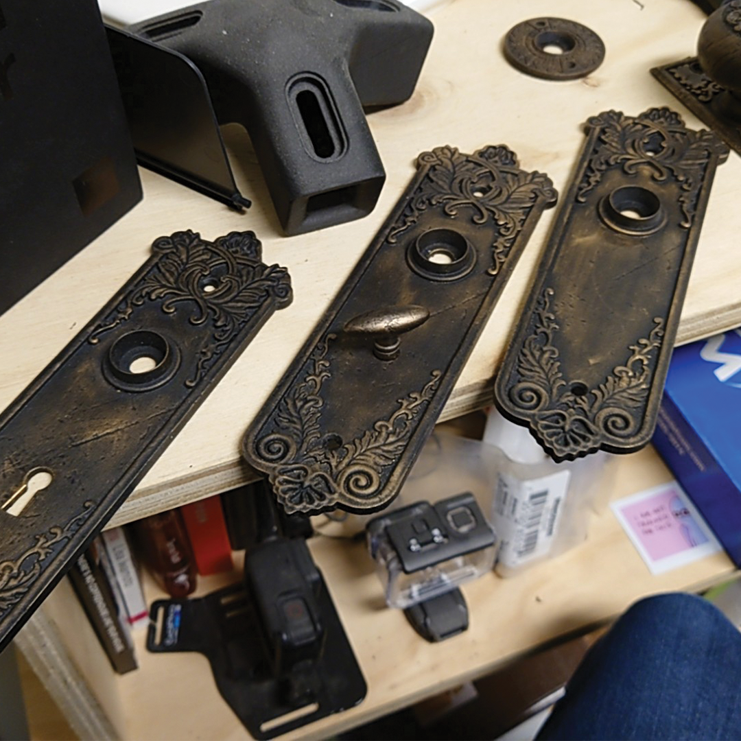
I’ll leave you with some renderings and final prototype photos below. All from the initial series, each printed and tested to make sure they are fully functional. The next step step up for me is to create something mechanical that’s hard to find and integrate smaller hardware such as springs and threads. The possibilities are endless.

Initial Antique Door Hardware Series